

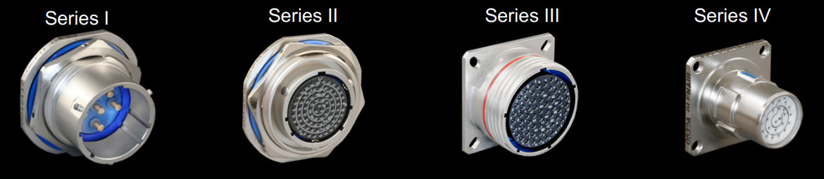
Previously known as MIL-C-38999, MIL-DTL-38999 connectors come in four series: Series I, Series II, Series III and Series IV. They are environmentally resistant connectors that use removable crimp contacts and have an operating range of -65 to +200°C.
Series I connectors are bayonet coupled and have high-vibration properties. They are scoop proof and are ideal for heavy wind and moisture environments. They are utilised when a fast disconnect coupling system is required.
Series II connectors are bayonet coupled, are non-scoop proof, and have a low profile, so are used when weight or space is limited, or in low-vibration, high moisture, and strong wind situations.
Series III connectors are coupled by a quick screw Tri start thread, are scoop proof, and are best suited for normal mating and unmating applications and can be used in high temperature, moisture, wind, or vibration environments when used with the correct accessories. Series III connectors are most commonly use in Military and Aerospace designs.
Series IV connectors are coupled by a Breech-Lok mechanism, are scoop proof, lightweight and suitable for blind mating applications, and they also have high-vibration attributes. They are well suited in high wind and moisture environments when used with the appropriate accessories.
| 38999 | Coupling | Scoop Proof | Durability | High Impact Schock | Bend Moment | Price |
|---|---|---|---|---|---|---|
| Series I | Standard Bayonet | Yes | 500 | Yes | 650 lbs in | $ |
| Series II | Low-Profile Bayonet | No | 250 | No | 150 lbs in | $ |
| Series III | Triple Start Threded | Yes | 500 | Yes | 1000 lbs in | $$ |
| Series IV | Breach-Lok | Yes | 500 | Yes – Heavy | 1000 lbs in | $$$ |
Shell Type

| Series III | Series IV | Shell Type Description | ||
|---|---|---|---|---|
| D38999/20 | D38999/40 | Receptacle, Wall Mount Flange | ||
| D38999/21 | D38999/41 | Receptacle, Box Mount, Hermetic | ||
| – | D38999/42 | Receptacle, Box Mount | ||
| D38999/23 | D38999/43 | Receptacle, Jam Nut Mount, Hermetic | ||
| D38999/24 | D38999/44 | Receptacle, Jam Nut Mount | ||
| D38999/25 | D38999/45 | Receptacle, Solder Mount, Hermetic | ||
| D38999/26 | D38999/46 | Plug, EMI Grounding Fingers | ||
| – | D38999/47 | Plug | ||
| D38999/27 | D38999/48 | Receptacle, Weld Mount, Hermetic | ||
Shell types 26, 46 and 47 are plugs. All other shells are receptacles. Odd numbered receptacle shell types denote hermetic construction: 21, 23, 25, 27, 41, 43 and 45.
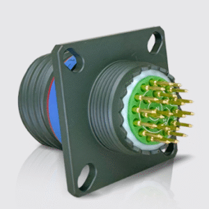
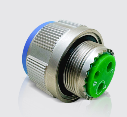
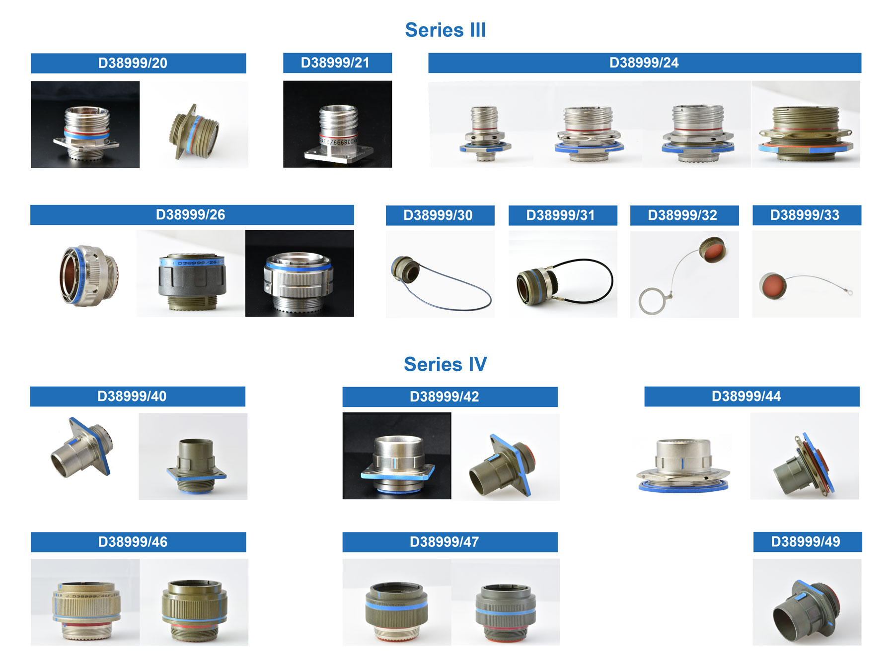 Examples of different D38999 shell styles
Material and Finish

| Code | Image | Material | Finish |
|---|---|---|---|
| F | Aluminum | Electroless Nickel Plated (48-hr. Salt Spray) | |
| G | Aluminum | Space-Grade Electroless Nickel (48-hr. Salt Spray) | |
| H | Hermetic | Space Grade | |
| J | Composite | Olive Drab Cadmium (2000-hr. Salt Spray) | |
| K | Stainless Steel | Corrosion-Resistant Stainless Steel – Firewall (500-hr. Salt Spray) | |
| L | Stainless Steel | Electrodeposited Nickel (48-hr. Salt Spray) | |
| M | Composite | Electroless Nickel Plated (2000-hr. Salt Spray) | |
| N | Hermetic | Stainless Steel, Nickel Plated | |
| S | Stainless Steel | Nickel Plated (500-hr. Salt Spray) | |
| T | Aluminum | Nickel PTFE (500-hr. Salt Spray) | |
| W | Aluminum | Olive Drab Cadmium (500-hr. Salt Spray) | |
| Y | Hermetic | Stainless Steel, Passivated | |
| Z | Aluminum | Black Zinc Nickel (500-hr. Salt Spray) |
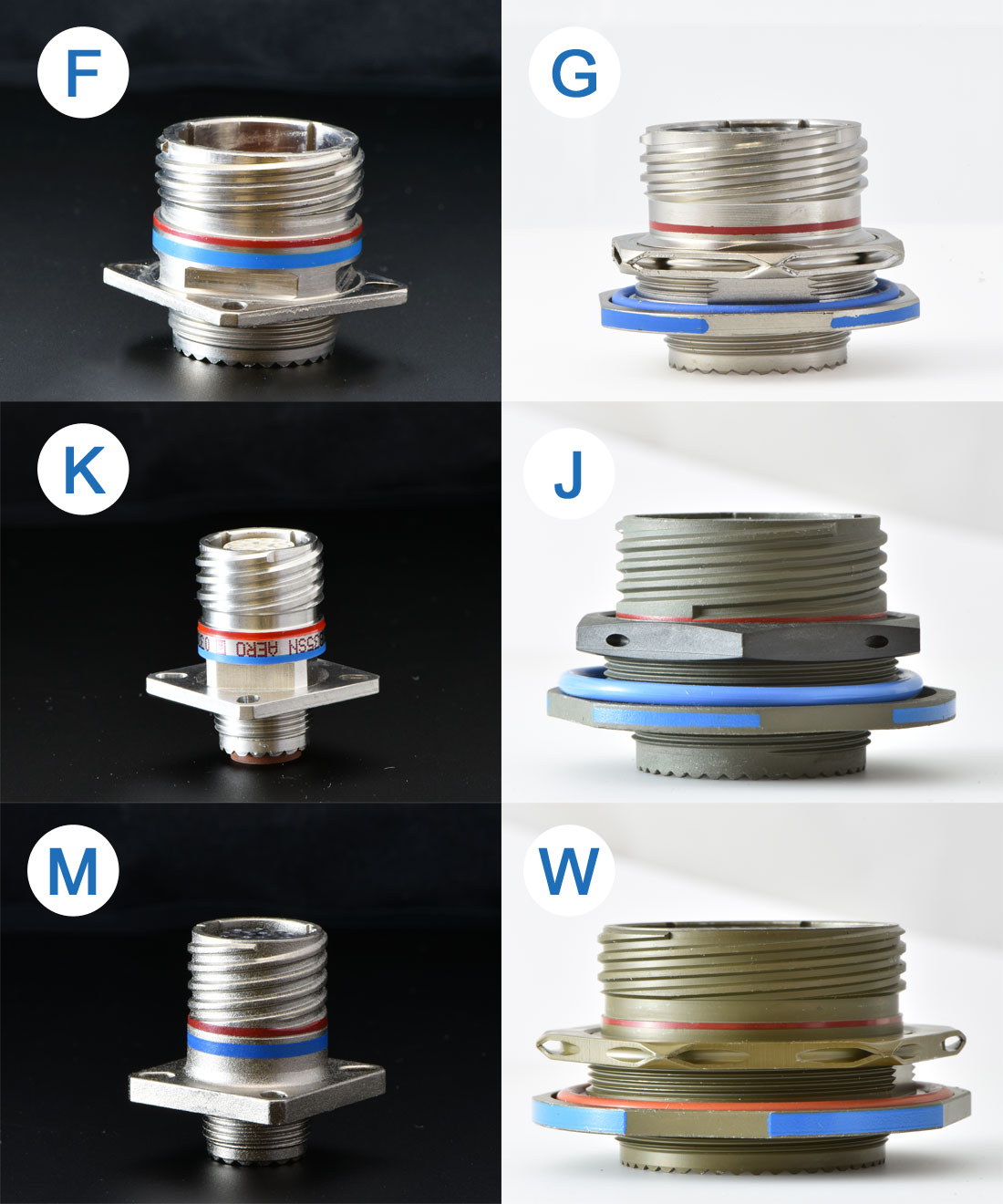 Examples of D38999 finish materials
Shell Size
 D38999 connectors are available in 9 shell sizes.
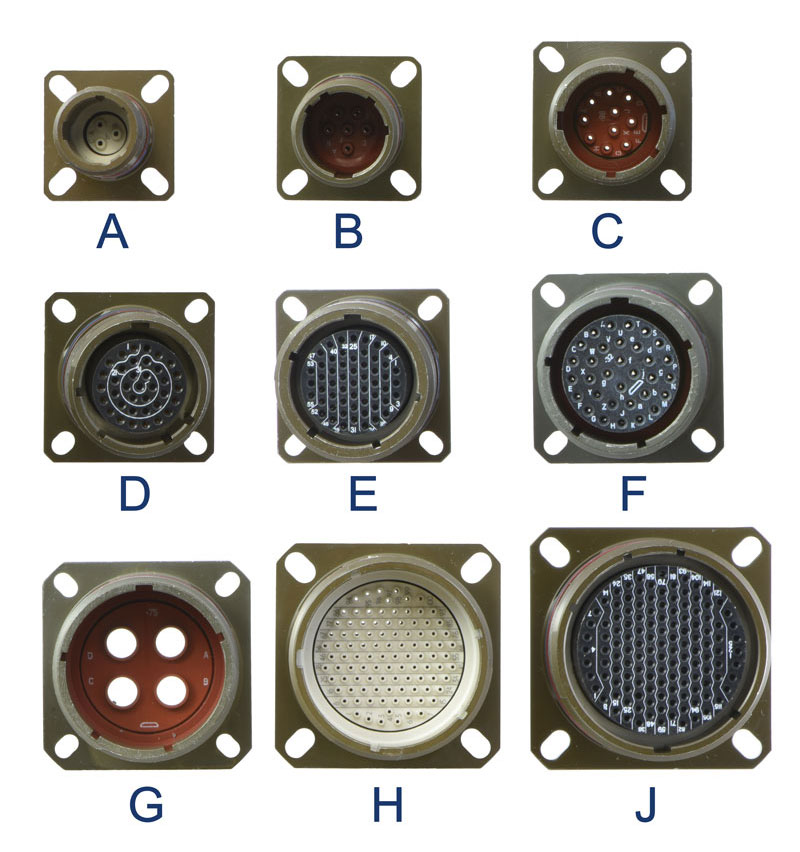 D38999 connector shell sizes: A, B, C, D, E, F, G, H ,J
Insert Arrangement

MIL-STD-1560 Insert Arrangements
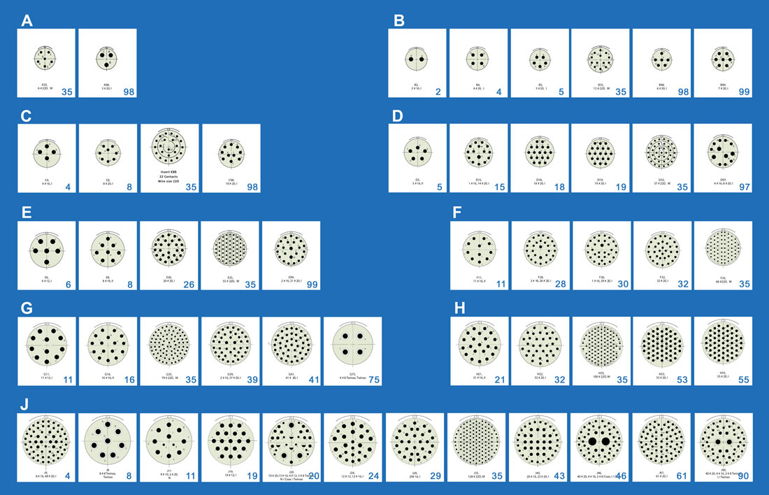
Connector Pin Counts
| Shell Size and Insert Arrangements | Number of Pins | ||||
|---|---|---|---|---|---|
| D38999 Series III | Service Rating | 22D | 20 | 16 | 12 |
| A35 | M | 6 | |||
| A98 | I | 3 | |||
| B2 | I | 2 | |||
| B4 | I | 4 | |||
| B5 | I | 5 | |||
| B35 | M | 13 | |||
| B98 | I | 6 | |||
| B99 | I | 7 | |||
| C4 | I | 4 | |||
| C8 | I | 8 | |||
| C35 | M | 22 | |||
| C98 | I | 10 | |||
| D5 | II | 5 | |||
| D15 | I | 14 | 1 | ||
| D18 | I | 18 | |||
| D19 | I | 19 | |||
| D35 | M | 37 | |||
| D97 | I | 8 | 4 | ||
| E6 | I | 6 | |||
| E8 | II | 8 | |||
| E26 | I | 26 | |||
| E35 | M | 55 | |||
| E99 | I | 21 | 2 | ||
| F11 | II | 11 | |||
| F28 | I | 26 | 2 | ||
| F30 | I | 29 | 1 | ||
| F32 | I | 32 | |||
| F35 | M | 66 | |||
| F45 | M | 67 | |||
| G11 | I | 11 | |||
| G16 | II | 16 | |||
| G24 | I | 24 | |||
| G25 | I | 25 | |||
| G27 | I | 27 | |||
| G35 | M | 79 | |||
| G39 | I | 37 | 2 | ||
| G41 | I | 41 | |||
| H21 | II | 21 | |||
| H32 | I | 32 | |||
| H34 | I | 34 | |||
| H35 | M | 100 | |||
| H36 | I | 36 | |||
| H53 | I | 53 | |||
| H55 | I | 55 | |||
| H97 | I | 16 | |||
| H99 | II | 11 | |||
| J4 | I | 48 | 8 | ||
| J19 | I | 19 | |||
| J24 | I | 12 | 12 | ||
| J29 | I | 29 | |||
| J35 | M | 128 | |||
| J43 | I | 23 | 20 | ||
| J61 | I | 61 | |||
| Shell Size and Insert Arrangements | Number of Pins | ||||
|---|---|---|---|---|---|
| D38999 Series IV | 22D | 20 | 16 | 12 | 10 |
| B5 | 5 | ||||
| B35 | 13 | ||||
| B98 | 6 | ||||
| B99 | 7 | ||||
| C4 | 4 | ||||
| C35 | 22 | ||||
| C98 | 10 | ||||
| D5 | 5 | ||||
| D18 | 18 | ||||
| D19 | 37 | 19 | |||
| D35 ??? | |||||
| D97 | 8 | 4 | |||
| E6 | 6 | ||||
| E8 | 8 | ||||
| E26 | 26 | ||||
| E35 | 55 | ||||
| F11 | 11 | ||||
| G41 | 41 | ||||
| H21 | 21 | ||||
| H35 | 100 | ||||
| H55 | 55 | ||||
| J4 | 48 | 8 | |||
| J11 | 2 | 9 | |||
| J19 | 19 | ||||
| J24 | 12 | 12 | |||
| J29 | 29 | ||||
| J35 | 128 | ||||
| J43 | 23 | 20 | |||
| J61 | 61 | ||||
| F32 | 32 | ||||
| F35 | 66 | ||||
| G11 | 11 | ||||
| G16 | 16 | ||||
| G35 | 79 | ||||
Contact Type

Sealed Connectors
| P | Pin |
|---|---|
| A | Less Pin |
| H | 1500-Cycle Pin |
| S | Socket |
| B | Less Socket |
| J | 1500-Cycle Socket |
Hermetic Connectors
| C | PC Tail Pin |
|---|---|
| D | PC Tail Socket |
| X | Eyelet Pin |
| Y | Eyelet Socket |
Contact Color Codes
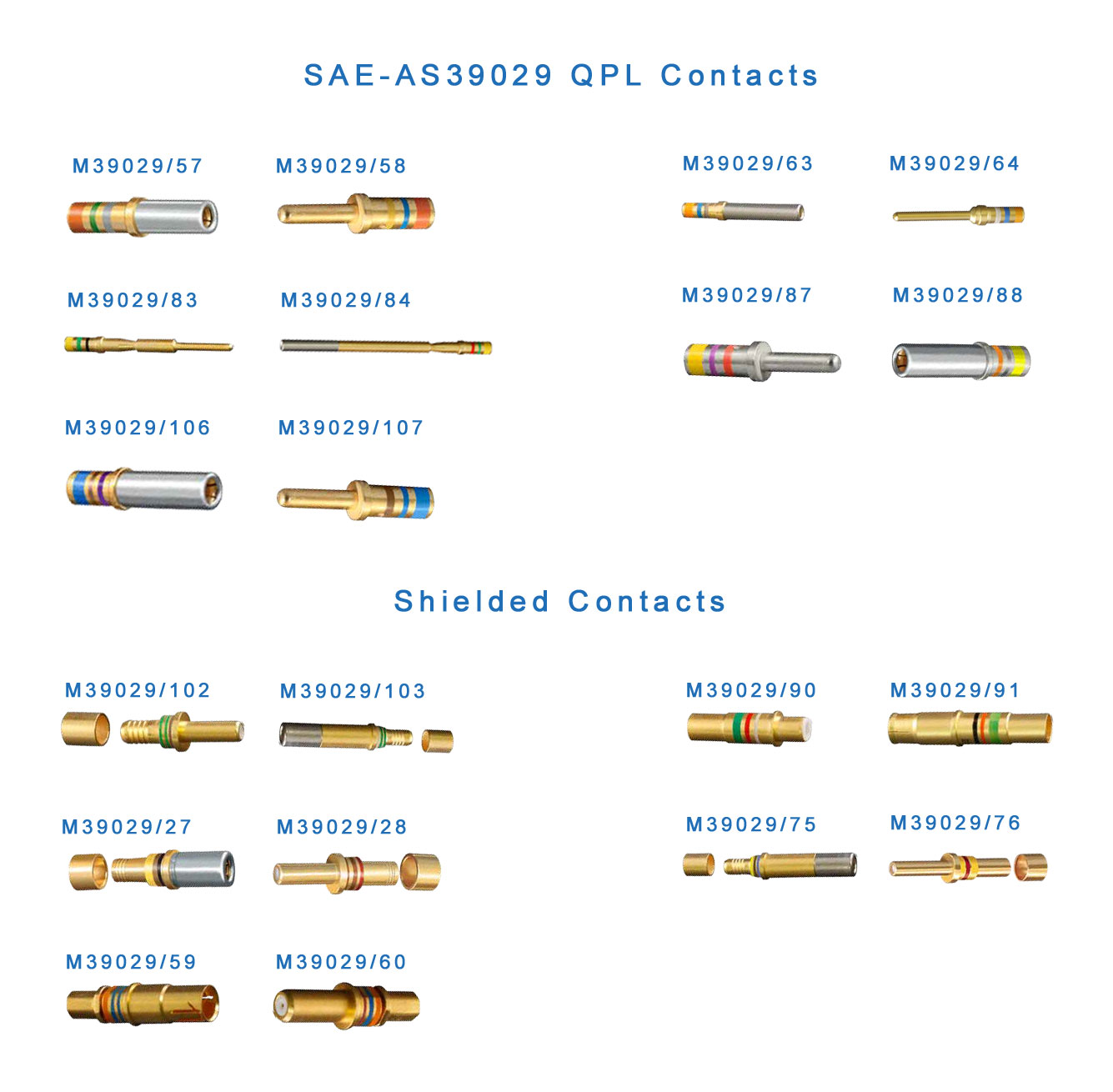 M39029 Contacts are used in D38999 connectors.
Keying Position
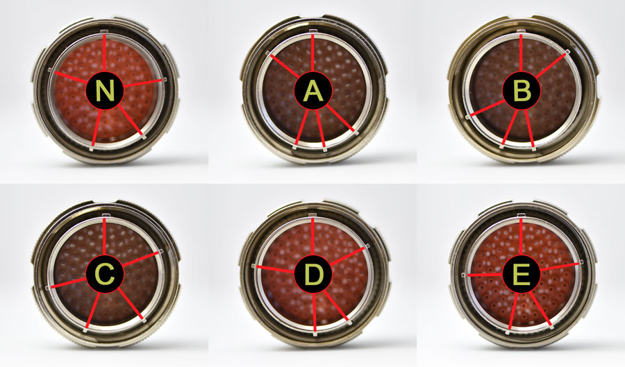
 There are six distinct keying positions available for each shell size in the D38999 series of connectors: N, A, B, C, D and E. The keying position is indicated by the last letter in the part number. A plug will only mate with a receptacle with the same keying code. The following figure shows different keying positions for D38999/26FJ61P plug.
Having 6 different keying positions allows use of up to six D38999/26FJ61P plugs in the same space without the possibility of mating a plug with incorrect receptacle.